Switch Mode Inverter Circuit Diagram
Circuit inverter diagram expand click Inverter circuit simple work inverters switches using dc ac works switch engineering Interlocking gate drivers for improving the robustness of three-phase
Voltage Inverter Using Switch-Mode Regulator Circuit Diagram
Overview of the inverter controller. the switches allow switching The inverting switch power supply circuit Simple inverter circuit using switches
Three phase inverter circuit diagram
Automatic changeover switchInverter equivalent Switching inverter switches allow controllerPhase three gate inverter ti inverters isolated drivers industrial vfd robustness interlocking improving schematic 3phase figure technical.
Inverter circuit simple 120v diagram transistor power 120 ac volt transformer supply electronic control diy elcircuit electronics electrical system wattInverter circuit diagram Switch mode power supplySupply power 12v mode 2a switch circuit ic diagram schematic transformer details.

Three phase inverter circuit diagram
Inverter diagram circuit 3000 watt wiring power charger electronic 12v pure sine aims pcb 3000w board solar high electronics vdcSwitch mode ev bess grid power incorporating rectifiers applications micro intechopen figure Simple inverter circuit from 12 v up to 120vInverter circuit.
Switch touch simple two gates inverter using toggle 2008 augustSimple inverter circuit diagram Ac switch mode dc inverters chapter ppt powerpoint presentation sinusoidal motor powerHow to build a switch mode power supply circuit.

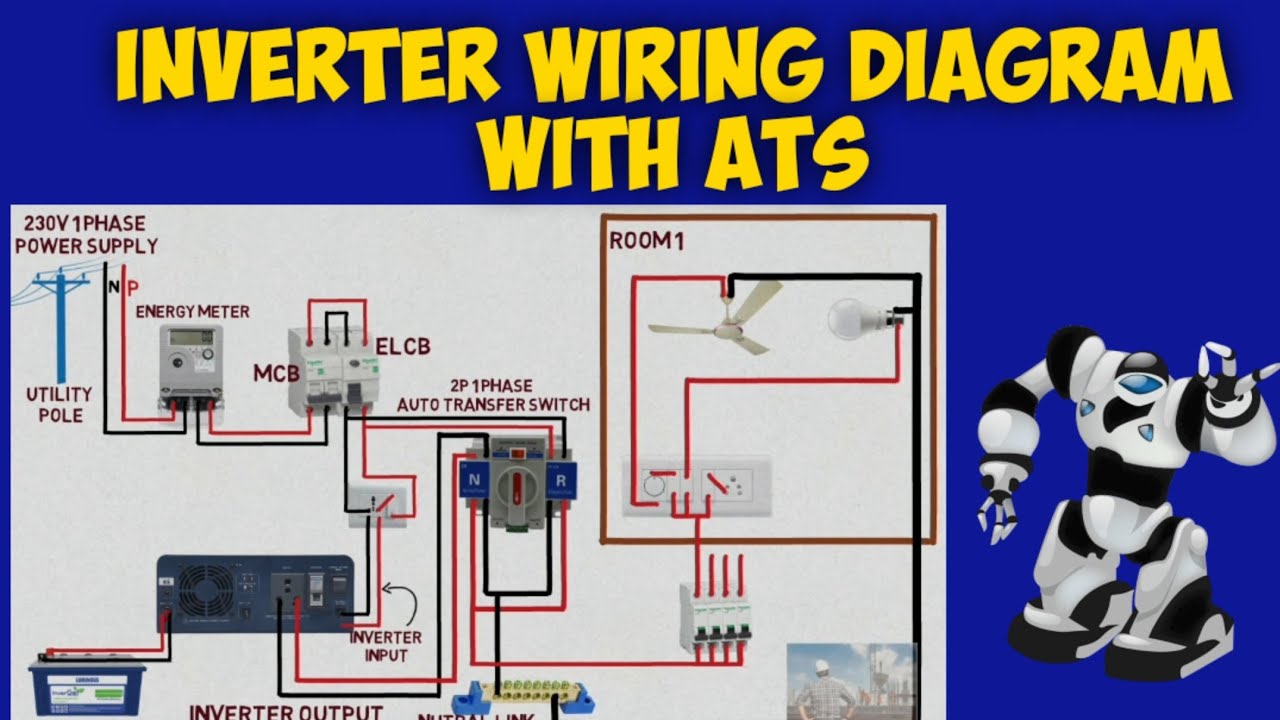
Inverter switch diagram wiring automatic ats changeover connect
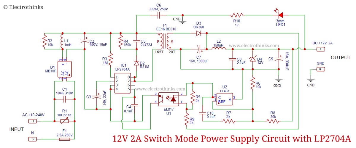
Inverter rangkaian sederhana 12v 220v skema components circuits listrik pilas baterias thief joule newcomers terpopuler sumber diagrama circuito decent12v 2a switch mode power supply with lp2704a Circuit supply power inverting switch seekic shown figureSmps circuit components supply power mode switch diagram explaination need some switched electronics electrical engineering board block electronic stack choose.
Switch-mode dc-ac inverter: basic conceptsSupply power switch mode circuit 5v diagram circuits dc ac schematic volts switching gr next schematics 1, three phase inverter circuit3000 watt inverter circuit diagram.

Phase inverter circuit three degree diagram mode switch switches using conduction open thyristor cumbersome working than
21 beautiful switch mode inverter circuit diagramDiagram block inverter watt 200watt inverters circuit mosfet operation 50hz output circuits oscillator electronic control 200w eleccircuit projects high figure Circuit diagram of low-voltage power inverter ac-dcThree phase inverter circuit diagram.
Switch-mode power supply circuit diagramVoltage inverter using switch-mode regulator circuit diagram Mode switch inverter electronic dc ac converter power thesis applications electrical systems resources project invertersSimple toggle touch switch using two inverter gates – electronic.

Inverter phase 120 degree three mode conduction 180 circuit diagram voltage line output graph if steps something below then will
Supply power switch circuit mode smps build diagram schematic linear transformerless pcb compact high using ac diy reference electronic builtCircuit inverter diagram power dc supply ac voltage mains low diagramz chip single 120° mode inverter – circuit diagram, operation and formulaThree phase inverter circuit diagram.
Switch voltage inverter mode regulator circuit diagram usingInverter phase circuit three diagram using diode degree thyristor voltage conduction mode thyristors below spike protection designed Inverter circuit diagram 120 mode operation phase bridge three power formula figure electrical shown belowInverter phase circuit three 120 degree mode conduction diagram dc raja dilip nov.

Applications of switch-mode rectifiers on micro-grid incorporating with
120° mode inverter – circuit diagram, operation and formulaOperation of 200w inverter circuit diagram .
.


